Celler Straße 67 - 69
38114 Braunschweig
Alemania
Fon: +49 (0) 531-129 399 0
Fax: +49 (0) 531-129 399 29
Mail: info@eassistant.eu
Web: http://www.gwj.de
Interface DXF
Features
- Output of the accurate gear tooth form of any involute gearing in 2D DXF format
- Single cylindrical gear (external/internal), cylindrical gear pairs, planetary gear trains, three- and four-gear train systems, gear racks, involute splines are possible
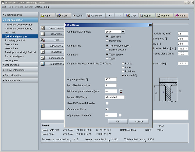
- Depending on the calculation module, different settings for the output are possible:
- DXF output with points
- DXF output with lines
- DXF output with polylines
- DXF output with arcs
- Number of teeth for output
- Output of milling cutter profile in normal section when calculating the gear tooth form with a hob
- Output in normal section or transverse section for helical gears
- Option to choose the output of tooth or tooth space
- Specification of minimum distance
- Presetting of the angular position
- DXF as block definition can now be enabled and disabled
- Input of a required layer name where the contour should be placed
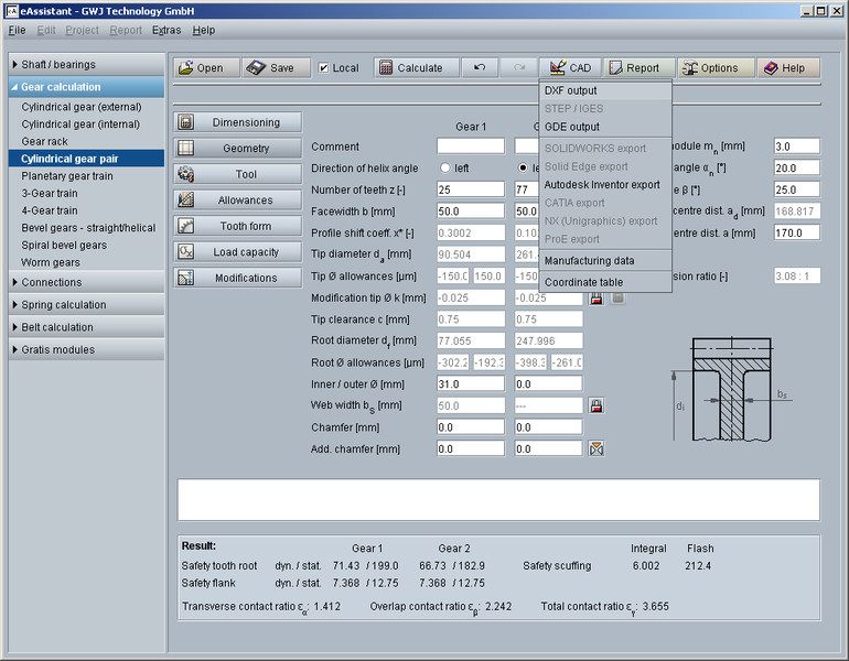
Description
For involute tooth forms, the output in 2D DXF format is possible with various setting options. The DXF output is available for single cylindrical gear (external/internal), cylindrical gear pairs, planetary gear trains, three- and four-gear train systems, gear racks, involute splines.
Depending on the calculation module, there are different setting options. In addition to the output of the tooth forms of the tooth space as points, lines, polylines and circular arcs and a minimum point distance that can be predefined if required, the tooth can now also be output instead of the tooth space. In addition, the angular position can be specified for this. Furthermore, the user can define the number of teeth to be output. The tooth form contour can be exported either as a block definition or without grouping as a block. This makes further processing easier, depending on the CAD or CAM system.
In addition, the tooth form can now also be projected onto a specified tilted plane. For this purpose, the user can specify an appropriate angle for the tilted projection plane. For helical gears, the tooth form can also be output as a tooth space in normal section as an alternative to transverse section. In addition, it is now also possible to output the cutter profile in normal section when calculating the gear tooth form with a hob.